Ikea Dioder LEDs Wifi controlled by FHEM

Motivation
A few years ago – while strolling through IKEA – i bought two sets of IKEA Dioder RGB LEDs. Then the ESP8266 32Bit Microcontroller became very popular. Now, i am running a FHEM Server for quiet a while. Eventually the idea grew to controlling the LED Strips/Bars via an ESP12-E from FHEM. At the very beginning i figured i would also have to write a perl module for FHEM to integrated with my ESP but it turned out an antsy guy from Hamburg already created one called Wifilight. It works for a dozen devices and so i just had to pick one and interpret what Wifilight is sending. A bit of browsing the code, googling and digging through the FHEM Forum turned out the LW12 LED Controller (german) implementation might be the one to try.
The Finished Project In Motion
Steps
The basic outline of the steps involved is fairly straight forward:
- Gathering hardware components
- Wiring stuff up on a breadboard
- Programming the ESP using the Arduino IDE
- Connecting to FHEM
1. Gathering Hardware Components
1 x ESP8266 Type ESP12-E
3 x N-Channel MOSFET with a maximum Gate Threshold Voltage of 3.3V (e.g IRLZ44NPBF)
1 x 12V to 3.3V Step-Down Module (e.g. LD1117V33)
Sidenote: If you do not have IDEA Dioder LEDs and intend to do a project like this…DO NOT BUY THEM! There are cheaper and better LED strips out there. The circuit and the code might have to be different in that case but there is plenty of information on the web on how to control other LED strips.
2. Wiring Stuff Up
I will not explain a lot about wiring the ESP. This can be easily looked up all over the web and most sources will say you need to pull up/down various more pins than i did. But the setup below works very well for me. I consider components like FTDI-Converters, breadboards, resistors, capacitors and all sorts of tools as given.
Upfront Thoughts
ESPs can’t stand input voltages over 3,3v. Also, all output voltages max at 3.3 volts logic level.
Always keep in mind that we are using 2 power rails because the LEDs work with 12 volts.
The layout of the ESP12-e does not fit strip-/breadboards so you could either solder your own IO adapter board or simply buy one.
Breadboard Layout

This layout shows my final setup. The button is used for resetting the ESP (because i had to do that a lot :) ) and the J1 male header pulls GPIO0 to GND which is necessary for programming. The connections for the FTDI module are missing here. MOSFETs Gate shouldn’t be floating so i used 10k resistors to pull them to GND. The voltage regulator (upper right corner in this picture) mentioned at point one got worrying hot for me so i simply attached a heatsink dismounted of an old mainboard. Please pay attention to GPIO15, it is connected to GND directly on the IO-Adapter of the ESP.
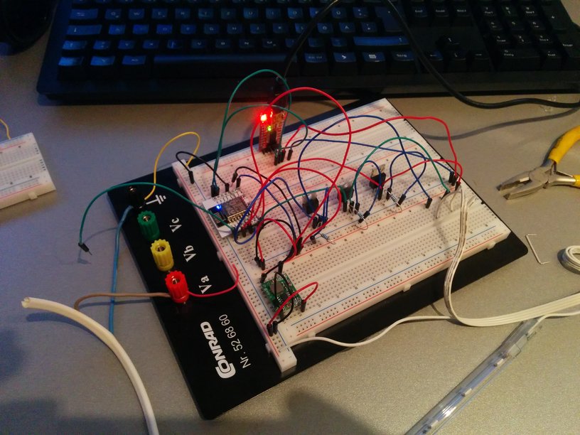
In reality the setup doesn’t look nearly that clean. I used a different step-down module to get 3,3V for the ESP while testing and programming the circuit.
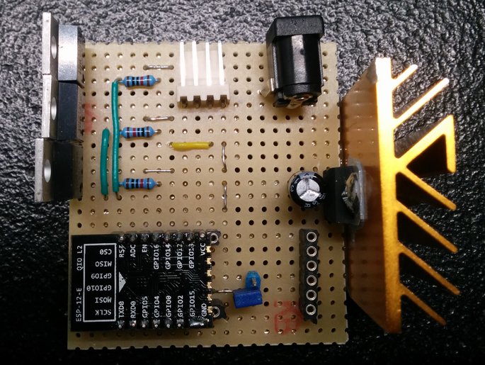
Poor Man’s PCB

Placement and wiring of all components for the final drilled board. Yellow wires are all run on top used to bridge unavoidable crossings and blue wires are going on the bottom of the board. The 3 single pin headers in the lower-right corner are used to represent the connection points of the 12V power supply. The 4 wires right above this headers are connected to the LED Stripts in bottom to top order: Red, Green, Blue, +12V
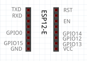
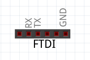
In the final layout the ESP was mounted upside down. So the pins align as shown in the left image. The picture on the right shows the FTDI connections of the header.
3. Programming the ESP
I was excited about the fact that the ESP8266 can be programmed using LUA. But there are multiple statements saying LUA renders the microcontroller rather unstable. So, without further ado and no verification whatsoever i gave Arduino’s C/C++ slang a shot and stuck to it.
The Arduino IDE
Setting up the Arduino IDE to work with the ESP and my FTDI module was almost straight forward
- Goto File -> Preferences -> Settings Tab
- Enter http://arduino.esp8266.com/package_esp8266com_index.json to the field labeled Additional Boards Manager URLs
- Goto >Tools -> Board -> Boards Manager…
- Filter for esp8266
- Select and install the latest version of the entry labeled esp8266 by ESP8266 Community
- The board settings working best for me are highlighted in yellow in the image below. Flash Size (marked red) worked in different variants. It became very important at a later stage when i added OTA-Update to the code. The setting shown was the only one that made OTA work reliable for me.

The Code
#include#include #include #include // GPIO definitions for LEDs #define red 14 #define green 13 #define blue 12 // Max values for PWM #define colorOnRed 1024 #define colorOnGreen 1024 #define colorOnBlue 1024 // Hardcode WiFi parameters const char* ssid = "....."; const char* password = "....."; // Define TCP Server on port 5577 WiFiServer server(5577); WiFiClient client = server.available(); // HTTP Push Update // curl -F "image=@firmware.bin" : /update ESP8266WebServer httpServer(80); ESP8266HTTPUpdateServer httpUpdater;
Line number 7 – 9 defines the GPIO pins to use for the MOSFETs Gate. ESPs have 10Bit PWM hence the maximum value for ~3,3V output is 1024 on lines 12 to 14. Line 17 – 18 takes the Wifi’s SSID and password. 21 to 22 defines a new object for our TCP Server we actually send our desired values to. Line numbers 26 and 27 define an HTTP-Server on port 80 for OTA-Updates.(I figured i’ll easily be annoyed by getting that little thing down the cupboard every time i decide to flash new software. So, being able to program it via HTTP with just a short curl-command is a feature i wouldn’t wanna miss anymore.)
void setup() {
  pinMode(red, OUTPUT);
  pinMode(green, OUTPUT);
  pinMode(blue, OUTPUT);

  Serial.begin(115200);
  WiFi.begin(ssid,password);
  Serial.println("");

  //Wait for connection
  digitalWrite(red, HIGH);
  while(WiFi.status() != WL_CONNECTED) {
    delay(500);
    Serial.print(".");
  }

  httpUpdater.setup(&httpServer);
  httpServer.begin();
  delay(10);

  digitalWrite(red, LOW);
  digitalWrite(green, HIGH);
  delay(3000);

  Serial.print("Connected to "); Serial.println(ssid);
  Serial.print("IP Address: "); Serial.println(WiFi.localIP());

  digitalWrite(green, LOW);

  // Start the TCP server
  server.begin();
  Serial.println("Server started");
}
Setting pin ‘red’ to HIGH is used for indication of the connection status. My RGB LEDs will stay red until the ESP got successfully connected to my WLAN (line 37 – 41). Once we got connected we start our HTTP-Update Server (43-44), turn red off (line 47) and green on for 3 seconds (48-49, 54). Last but not least we start the TCP Server (line 57).
void loop() {
  // For push flashing only
  httpServer.handleClient();

  // Check if a client has connected
  WiFiClient client = server.available();
  if (!client) {
    return;
  }

  // Wait until the client sends some data
  // Serial.println("new client");
  while(!client.available()){
    delay(1);
  }

  int buflen = 8;
  byte inputbuf[buflen];
  client.readBytes(inputbuf, buflen);
  client.flush();

  /*
  // DEBUG
  Serial.print("Byte 0: "); Serial.println(inputbuf[0]);
  Serial.print("byte array length: "); Serial.println(sizeof(inputbuf));
  Serial.print("last byte: ");  Serial.println(inputbuf[sizeof(inputbuf) - 1]);
  */

  // Find startbyte (LW12 connection of FHEM's Wifilight module)
  int startbyte;
  for (int i = 0; i < buflen; i++) {
    if (inputbuf[i] == 86 and inputbuf[i + 4] == 170) {
      startbyte = i;
    }
    /*
    // DEBUG
    Serial.print(i); Serial.print(": "); Serial.println(inputbuf[i]);
    */
  }

  int redval = map(inputbuf[startbyte + 1], 0, 255, 0, colorOnRed);
  int greenval = map(inputbuf[startbyte + 2], 0, 255, 0, colorOnGreen);
  int blueval = map(inputbuf[startbyte + 3], 0, 255, 0, colorOnBlue);

  /*
  // DEBUG
  Serial.print("redval: ");  Serial.println(redval);
  Serial.print("greenval: ");  Serial.println(greenval);
  Serial.print("blueval: ");  Serial.println(blueval);
  */

  analogWrite(red, redval);
  analogWrite(green, greenval);
  analogWrite(blue, blueval);


  client.flush();
  delay(1);
  //Serial.println("Client disonnected");

  // The client will actually be disconnected
  // when the function returns and 'client' object is detroyed
}
Line 89 - 98: Looking at the LW12 connection of FHEMs Wifilight.pm we can see that it is sending 0x56, 0, 0, 0, 0xAA. The first byte is always 86 then it provides us with 3 bytes of RGB values from 0-255 and ends with 170. But, if the on command is issued by FHEM we get first 0xCC, 0x23, 0x33 followed by the first sequence. So, this iteration is only used to determine where the data resides we are interested in.
Line 100 - 102: As described above, is our PWM 10 bits wide. FHEM sends 8Bit wide values, so map() is used to transform 0-255 to the representative 0-1024 values.
Line 111-114: Well, set our pins. :)
Actual Files on Github
4. Connecting to FHEM
Teaching FHEM about the new "esp-ikea-led" is by far the easiest part.
telnet localhost 7072
defineWifiLight RGB LW12:
seton
setHSV 0,100,100 #red set HSV 120,100,100 #green set HSV 240,100,100 #blue
It might be necessary to play a bit with the attributes set by default:
Attributes:
   colorCast  0, -20, -20, -25, 0, -10
   whitePoint 1, 0.75, 0.25
The Result
Bottom View
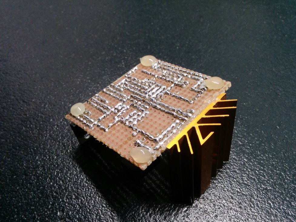
As you can tell, soldering is not exactly a point to put on my "Strengths List" but it worked straight from try one. I have to admit that i was surprised because i expected at least a few shortenings.
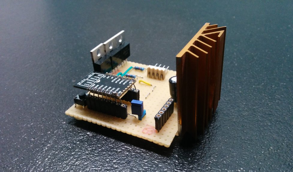
Top View
As mentioned earlier in that post, i used an old heatsink borrowed from a mainboard to cool down the voltage regulator. It is oversized and makes the whole circuit-board chunky.
3 things i immediately regretted on that board
- The capacitor should move a bit further from the LD33V.
- The J1 jumper (for programming) should move somewhere else as it is hard to reach when the FTDI converter is attached.
- I am not sure if it is a good idea to have the MOSFETs packed so close.
Product Picture
Well, i can't say it's ready for production line but i sort of like how it turned out.
Moving In
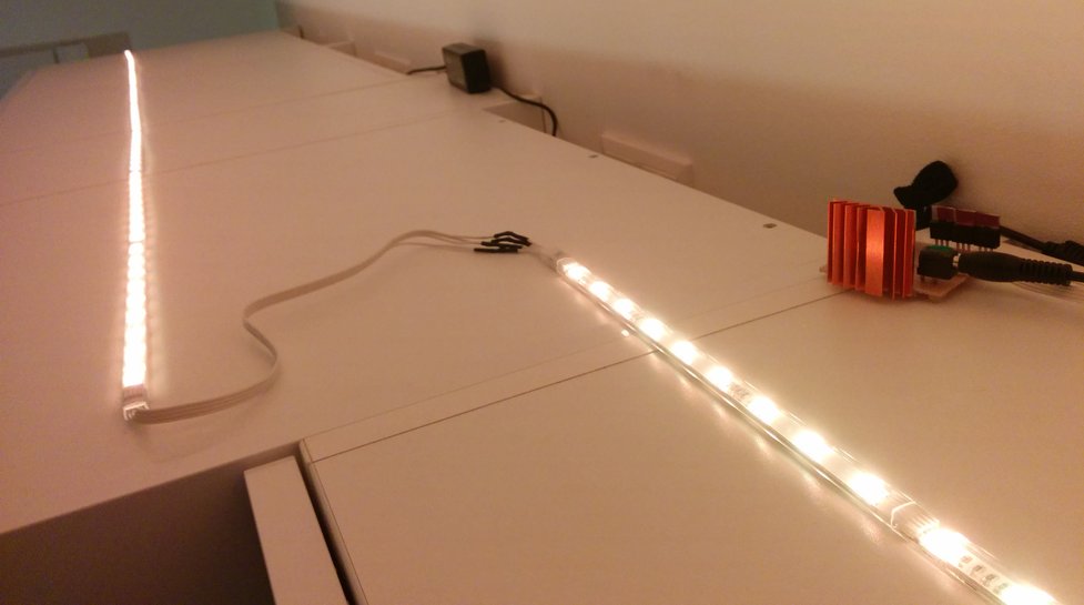
Moved to it's new home...on top of the cupboard.
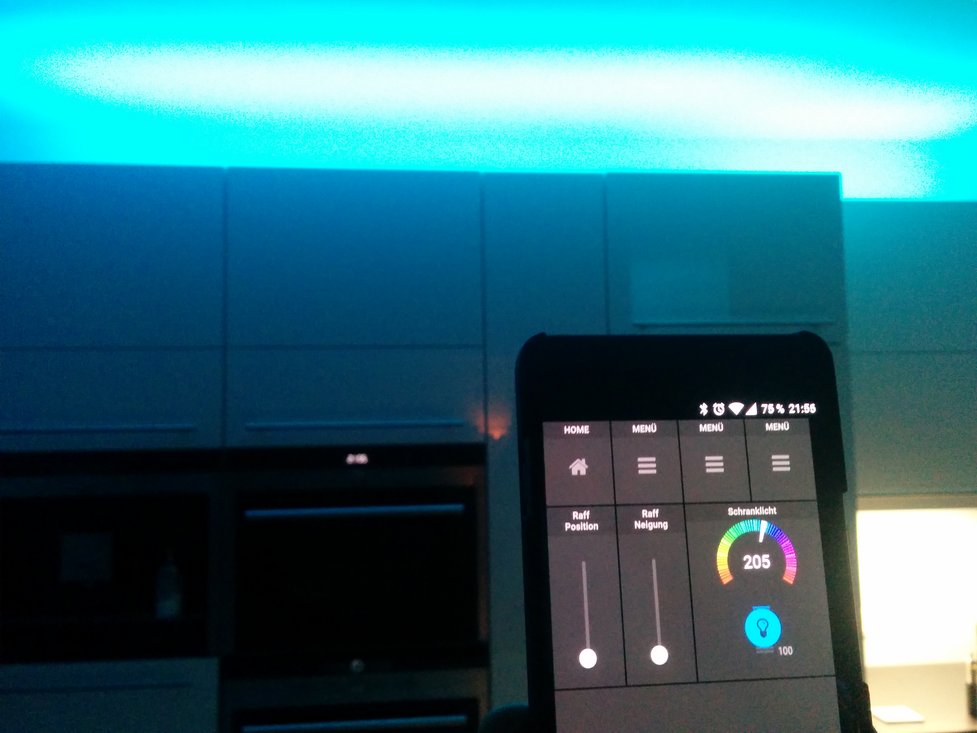
In the end...there is light.